DIFFERENTIAL PAIR SETUP
Introduction
While much of the differential pair work is specific to the layout, there are two tasks required on the schematic: you must identify the pins that form each pair, and you must name the pair so that the layout has a class to route it under.
Both tasks are reached from right click context menus on the schematic.
- Right clicking on one of the two wires of the pair gives you Configure Diff. Pair, which opens the Differential Pair Configurator. This is the dialogue that the rest of this topic describes.
- Right clicking on a component gives you Configure diff. pair pins, which declares which of that component's pins are paired with which. Declaring the pairs on the component is worth doing first where a part is used in several designs, because the declaration then travels with the part.
- Right clicking on a component also gives you Configure pass-through pins, which declares the pins that a signal passes through on its way between the source and the destination, for example the two sides of a series termination resistor or a common mode choke.
Use terminals and terminal names, not junction dots and wire labels, when wiring a differential pair. The configurator follows the signal through named terminals.
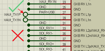
Use terminals and terminal names, not junction dots and wire labels
Workflow
Once everything is placed and wired on the schematic, the workflow in the Differential Pair Configurator is as follows.
- Name the pair in the Diff. Pair Class field, using Select New DP Class if the class does not exist yet.
- Identify the Source Component, the part the signal originates from.
- Identify the Destination Component, the part the signal terminates at.
- Set Pin 1 and Pin 2 for the Source Component.
- Set Pin 1 and Pin 2 for the Destination Component, if the configurator has not worked them out for you.
- Use Manage Passthroughs to deal with any components the pair passes through, again if this has not been resolved automatically.
- Save and exit when the configurator shows a complete signal path.
Component minimum pin count filters the component lists so that you are not scrolling past every passive on the sheet. Manage Existing Paired Pins lets you review and edit pin pairings you have already declared.
The full process, along with some worked examples, is covered in the layout module help as linked below.
See Also: